So after struggling for a while, giving up and coming back to it, I just finished up wiring my cruise control on the 85C10 with the 5.3L in it. This will only apply to a drive by wire throttle body motor.
Essentially, theres 5 wires to make this work. Super easy.
My problem was a broken brake switch on my truck. I had cruise control before, so there is a wire on the brake switch that is 12 V hot without the brakes pressed, open circuit when they are pressed (power goes to stop lights instead)
My truck was not putting power to that wire, and for safety, GM's computer needs to see the switch between the two circuits before cruise will work.
Instead of looking for a new brake switch right now, I used a relay to change the signal. That signal is for the TCC as well for torque converter lockup, so two birds with one stone.
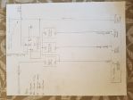
Heres the Diagram, and Ill explain it below
I dont know how to rotate it, maybe someone can help me out...
But essentially I did mine with three switches becuase the column cruise wires always crack where they come out. I re soldered new ones on to the factory switch and before I could figure out the brake switch was screwed, the new wires broke, so screw it.
You will need either a factory switch (some work some dont. You need to maintain power to the cruise on switch while operating the other functions, some from the 70's dont, dakota digital doesnt in some cases, just a heads up), or a toggle switch that keeps power at all times, and two momentary switches.
Power from the fuse panel comes through the first switch, then you ladder the wires out of the switch into the "Cruise On (GREY)" wire from the TAC Module, and also into the back side of the other two momentary switches.
The output from the momentary switches power the "Set/Coast(Dark BLue)" wire and the "Resume/Accel(Grey/Black)" Wire on the TAC Module
The light blue wire from the TAC Module goes to the wire that gets 12V+ when brakes are applied. (LED Brakelights Cause Problems with this sometimes, it need to see resistance too)
Now if my brake switch wasnt broken, that'd be it for wiring, because I already hooked up my TCC wire (ill assume you have it hooked up already, because you need it for the swap if youre running an auto (maybe stick too im not sure))
So I used a relay to provide constant power to the TCC wire, but when you hit the brakes, it goes off.
Pin 30 is not used
Pin 85 is ground
Pin 87a goes to TCC
Pin 86 12V with brakes applied
Pin 87 Constant Fused Power
(PLEASE USE A FUSE, and PLEASE CHECK WIRING TO MATCH MY EXPLANATION. SOME RELAYS ARE DIFFERENT #s)
Brief explanation and im done.
The constant battery power flows constantly from 87 to 85, but also provides NC power to 87A, or the TCC wire. When you hit the brakes, power from the brakes triggers the solenoid, and changes power on 87A to NO, cutting the signal. When the brakes are released, power is restored to 87A
Hopefully this can help someone at some point in time. Might just be a good morning read. Ill leave it here.